Design
Design for casting: seven moves to make a part castable
Seven changes that recur when a drawing is made ready for casting. Most of them make the part cheaper, and several make it stronger as well.
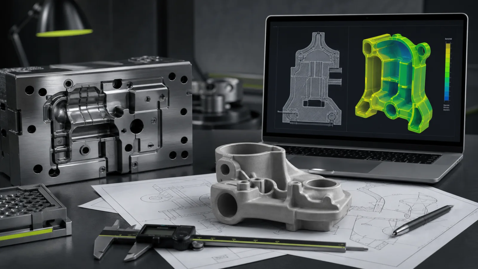
We review castability before we quote. We call it positive product criticism, and the same seven points come up again and again.
Here they are, in order of importance.
1. Make the wall even — not just thin
The most common misunderstanding is that wall thickness is about saving metal. It is also that, but it is not the main point.
The main point is that uneven walls ruin the part.
Where the section is locally thick, the metal solidifies last. That is where shrinkage voids form — cavities created because liquid metal contracts as it becomes solid and receives no feed. And they land precisely where the designer often thought extra strength was being added.
Uneven thickness also produces distorted parts. Thin areas solidify and contract first, thick areas afterwards, and the part twists.
Thick sections also cost twice: more metal per part, and a longer cycle because solidification takes longer. You pay for the cycle on every single shot, for the whole life of the series.
The move: core out everything thicker than necessary. Use ribs instead of solid metal. Aim for even wall thickness throughout the part.
2. Put draft on everything in the draw direction
Without draft the part sticks in the die. Metal shrinks onto the cores as it solidifies, and a perfectly vertical wall drags against the steel through the entire ejection stroke — or is torn by the ejector pins.
As general practice, internal faces need more draft than external ones, because the part shrinks away from the outer walls and onto the cores. Deep ribs and tall cores need more than shallow ones.
What people forget: draft affects dimensions. A wall 3 mm thick at the top is thicker at the bottom. If the thickness is critical, the drawing has to say where on the face the dimension applies.
The move: put draft on everything, and state where critical dimensions are to be measured.
3. Put a radius in every internal corner
A sharp internal corner does three unhelpful things at once:
- It concentrates stress in the part and becomes the starting point for fatigue cracks.
- It creates a local accumulation of metal where solidification finishes last.
- It leaves a sharp edge in the steel tool, which cracks under thermal load.
Radii fix all three. They cost nothing — the tool is machined anyway — and they make the part stronger, not weaker.
This is the cheapest design change there is, and one we often propose.
4. Core the bosses out from behind
Bosses are the most common source of shrinkage porosity in a cast housing.
Where the boss meets the wall the section doubles. That is where the metal solidifies last. That is where the void appears — directly under the screw, which is exactly where the part has to carry load.
The move: core the boss out from the back so the wall thickness stays even, and tie the boss to the wall with a rib rather than blending it in.
If the boss is to be threaded, the hole also has to be cast at the right diameter. Too tight gives hard tapping and broken taps. Too large leaves the thread without enough material to bite into.
5. Use ribs instead of solid metal
A rib moves material away from the neutral axis, where it does work, instead of placing it in the middle of the section where it only adds weight. The principle is the same as in an I-beam.
A ribbed structure is stiffer than a solid one of the same weight, and it casts better.
The rule: the rib should be clearly thinner than the wall it sits on, or it creates a new accumulation of metal where they meet. Give it draft and a radius at the root.
In sheet metal every stiffener costs an operation. In casting the rib comes with the shot. That is one of the main reasons a cast bracket can be made lighter than a welded one.
6. Remove the undercuts you can live without
An undercut is anything that grips the tool and prevents the part releasing straight out: a hole in the side, a groove, a hook, a thread across the draw direction.
The remedy is a slide core — a moving part of the tool that withdraws sideways. Technically that is unproblematic, but it costs: a more expensive tool, a longer cycle, an extra parting line on the part, and one more mechanism that can wear or jam.
Often the undercut can be removed with a small geometry change that does not affect the function at all. A side hole can be moved into the draw direction. A groove can be machined afterwards.
The move: go through the part once and ask of each feature: does this release straight out? Where the answer is no, ask: does it have to be like that?
This is often the single largest saving in the whole project.
7. Specify tight tolerances only where the function demands it
The most expensive line on a drawing is often the general tolerance class in the title block.
Writing the finest class “just to be safe” makes the whole part more expensive to produce and to inspect, with no functional gain. Every dimension tighter than casting can hold has to be machined — and then material has to be added, only to be removed again.
The move: set a generous general class, and specify tight tolerances explicitly on the five or six dimensions that actually determine the function.
Two details that help a great deal:
Set the datums from the seating face, not from the outer edge of the part. A casting has draft on every external face, and a dimension taken from there is taken from a face that is not perpendicular to anything.
Avoid critical dimensions crossing the parting line. Dimensions spanning the parting line always carry a looser tolerance than dimensions within one die half, because they are affected by how the two halves align. If a critical dimension sits there, it can often be moved.
Bonus: mark the visible faces
If the part is visible to the end user, mark it on the drawing. We will then place the parting line and the ejector points outside the field of view.
This is built into the tool and cannot be corrected afterwards without a rebuild. It is the one decision that absolutely has to be made before the tool is designed.
The defects these moves prevent
The seven moves above are not aesthetics. Each of them prevents a specific casting defect, and it is worth knowing the defects by name — they turn up in non-conformance reports and in feedback from the foundry.
Cold shut happens when two fronts of melt meet after both have begun to freeze. They lie against each other without fusing, and the result is a visible line that is also a weakness. Thin walls far from the gate and runner are the usual cause, and even wall thickness is the main defence.
Hot tearing happens while the part is still hot and weak: the metal shrinks, the die holds it back, and the material tears at a sharp internal corner. That is why a fillet radius is not a detail — a sharp transition is where stress collects exactly when the material can take least.
Shrinkage porosity belongs to the same family and is governed by the same thing: where the metal freezes last. If the heavy section sits far from a feeder (riser), there is nothing to feed it with while the part shrinks, and the void stays inside the wall.
Two of the moves are about getting the part out at all. Draft angle is the taper that lets the part release from the steel; without it the part drags, and dragging is both a surface defect and die wear. Ejector marks are where the pins push — small circular witnesses that have to be placed where they do not matter, which is a decision taken in the tool and not afterwards.
All of it is what DFM — design for manufacturability means in practice: taking the decisions in the CAD model, where they are free, instead of in the tool, where they are not.
When to get in touch
Before the design is locked.
All seven moves above are changes to the geometry. Once the drawing has been approved internally at your end it is hard to change — and then you are left with a part that can be cast, but costs more than it needed to.
Send the drawing, the model or the sketch. You get a review of all seven points, and it costs nothing.
- DFM
- draft angle
- wall thickness
- radius
- design