Quality
Casting tolerances: ISO 8062 and tolerance grades explained
A tolerance class is not a single number but a table. Here is how ISO 8062 and ISO 2768 fit together, why the parting line changes everything, and the four mistakes that make a drawing needlessly expensive.
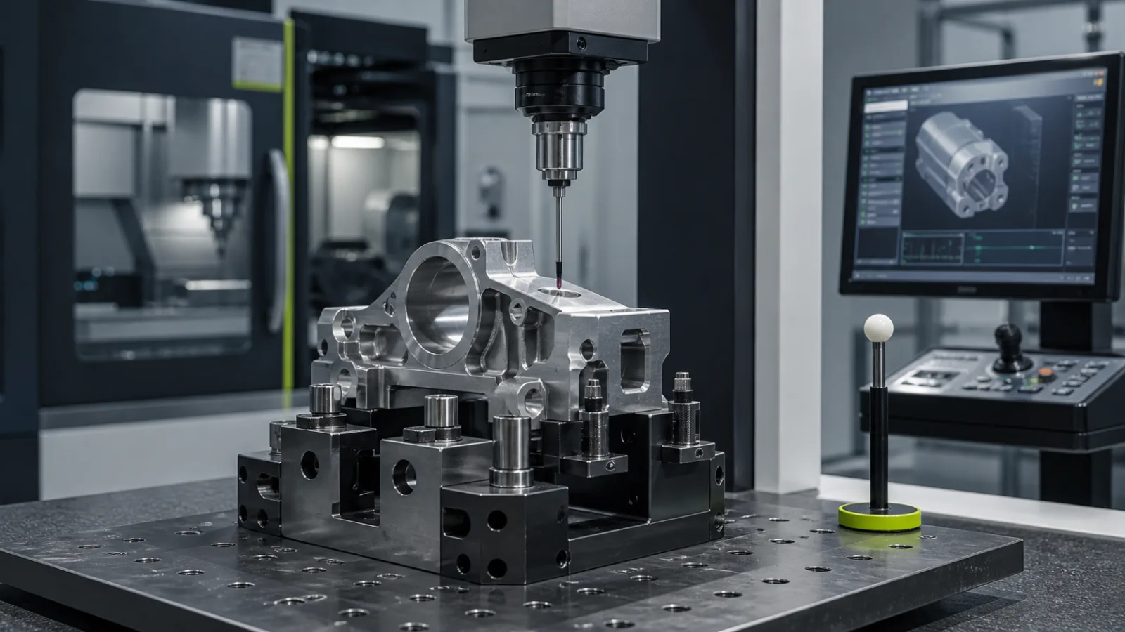
A high degree of accuracy is not a tolerance. It is a feeling.
If two parties are to agree on what is inside and what is outside, a class has to appear on the drawing — and that class has to be the right standard for the right kind of dimension.
Two standards, two areas of use
ISO 8062 covers dimensions that come directly from the casting process. It defines DCTG grades for dimensional tolerances and RMA values for the required machining allowance. This is the standard for everything that will not be machined.
ISO 2768 covers general tolerances on machined dimensions that carry no individual tolerance on the drawing. The classes for linear dimensions are f (fine), m (medium), c (coarse) and v (very coarse), with a second letter — H, K or L — for form and position tolerances.
A cast and partly machined part needs both. One class for what is as cast, one for what is machined. If only one of them appears on the drawing, the supplier guesses at the rest.
A tolerance class is a table, not a number
This surprises more people than it should.
Within the same class, larger deviations are permitted on large dimensions than on small ones. That is logical: shrinkage and die wear act proportionally, not in absolute millimetres. A dimension of 200 mm therefore gets a wider tolerance band than a dimension of 10 mm in the same class.
Practical consequence: you cannot read off class X gives plus or minus 0.2 mm. You have to see which size range the dimension in question falls into.
What is achievable, and why
Which class can be held depends on the process. As general industry knowledge, high pressure die casting is tightest, gravity casting sits in the middle and sand casting is loosest.
The reason is how much moves. In die casting a steel die is filled under pressure, with controlled cooling and small tolerances in the tool itself. In sand casting the mould is made afresh for every pour, from a material that has tolerances of its own.
But the process alone does not decide. Three other things matter just as much:
Part size. Large parts shrink more in absolute terms, and the shrinkage is not perfectly uniform.
Geometry. A part restrained by cores contracts differently in different directions. Uneven wall thickness amplifies this.
Where the tool is in its life. A new die holds tighter dimensions than one that has run several hundred thousand shots.
The parting line changes everything
This is the single point that gives a designer most in return, and it rarely appears in textbooks.
Dimensions within one die half are the tightest you can get. They are determined by one piece of steel, machined in one setup.
Dimensions crossing the parting line additionally depend on how the two die halves align — and on how much flash has built up along the parting line as the tool wears. They are always looser.
The consequence is practical: if you have a critical dimension spanning the parting line, say so early. It can often be moved, either by changing the geometry slightly or by putting the parting line somewhere else. Both are free before the tool is designed and impossible afterwards.
Machining allowance is part of the tolerance question
If a face is to be machined, it has to be cast with material to remove. That is what ISO 8062 calls RMA — required machining allowance.
The allowance has to be large enough for the whole face to clean up even when the casting tolerance runs the unfavourable way. That is the entire reasoning: the allowance is dimensioned against the tolerance, not against an average part.
At the same time it has to be small enough that you are not paying for metal and cutting time you do not need.
Practical advice: say in the enquiry which faces will be machined. The allowance then goes exactly there, and nowhere else.
The four mistakes that make a drawing expensive
1. A fine general class in the title block “just to be safe”. This is the most expensive line on many drawings. It makes the whole part more expensive to produce and to inspect, with no functional gain. Set a generous general class and specify tight tolerances explicitly where they are needed.
2. The same tolerance on everything. A part usually has five to ten dimensions that actually determine the function. The rest only have to be roughly right.
3. Datums set from the outer edge. A casting has draft on every external face. A dimension taken from there is taken from a face that is not perpendicular to anything and that changes with height. Set the datums from the seating face — the face that actually meets the customer part.
4. A tolerance without saying where it is measured. On a drafted face the thickness differs between top and bottom. If the thickness is critical, the drawing has to say where the dimension applies.
What to ask the supplier for
- Which DCTG grade is held as cast for your part?
- Which ISO 2768 class applies to machined dimensions?
- How much machining allowance is applied, and on which faces?
- Which of your critical dimensions cross the parting line, and can they be moved?
- How are the dimensions verified, and do you get a measurement report?
We state the tolerance class per part in the quotation — both as cast and after machining — rather than publishing one general figure that would be wrong for half the parts anyway.
Send the drawing with the critical dimensions marked. We will tell you what is achievable, what has to be machined, and what could be made cheaper by moving a dimension a few millimetres.
- tolerances
- ISO 8062
- ISO 2768
- machining allowance
- parting line